How is Network Bonding Used in Oracle VM?
Network bonding refers to the combination of network interfaces on one host for redundancy and/or increased throughput. Redundancy is the key factor, it is desirable to protect the entire virtualized environment from loss of service due to failure of a single physical link. This network bonding is the same as the Linux network bonding or Oracle Solaris data link aggregation. Using network bonding in Oracle VM may require some switch configuration.
Important
While Oracle VM Manager uses the Linux terminology for network bonds, Oracle Solaris users should understand this to be equivalent to data link aggregation.
In Oracle VM, there are three modes of network bonding:
- Active Backup or Active-Passive (mode 1): There is one NIC active while another NIC is asleep. If the active NIC goes down, another NIC becomes active. While this mode does not increase throughput, it provides redundancy in case of failure. Active Backup is a safe option if you intend to make use of VLANs.
- Dynamic Link Aggregation or Link Aggregation (mode 4): Aggregated NICs act as one NIC which results in a higher throughput, but also provides failover in the case that a NIC fails. Dynamic Link Aggregation requires a switch that supports IEEE 802.3ad. Dynamic Link Aggregation is the preferred mode of network bonding, but requires that the network is configured correctly on the switch. Furthermore, you should be aware that there are significant cabling requirements. An initial guideline is that all of the Ethernet ports aggregated into a single bond using this bonding mode must be connected to the same switch.
- Adaptive Load Balancing or Load-Balanced (mode 6): The network traffic is equally balanced over the NICs of the machine and failover is also supported to provide redundancy. Unlike Dynamic Link Aggregation, Adaptive Load Balancing does not require any particular switch configuration. Adaptive Load Balancing is only supported in x86 environments. Adaptive Load Balancing may not work correctly with VLAN traffic.
Note
Adaptive Load Balancing (mode 6) is currently not supported for SPARC servers.
During installation of Oracle VM Server, the network interface (selected when prompted for the management port) is configured as a bonded interface. The bond is created with only one interface. This is done because the reconfiguration of the management interface on the Oracle VM Servers is not supported. You can add a second interface to the already existing bond device without affecting the configuration of the original interface. This is illustrated in Figure 5.2, “Network bonding”, where a second network interface is added to bond0, the network bond created during installation. By default, the bond mode is set to Active Backup for the management network.
Figure 5.2, “Network bonding” also illustrates the configuration of a second bonded interface, bond1, which can be used for other network usage, such as the virtual machine channel. Separation of network functions into different channels is discussed in more detail in Section 5.6, “How are Network Functions Separated in Oracle VM?”.
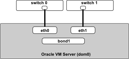
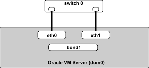
It is important to understand that the actual cabling of Ethernet interfaces is important when using network bonds. If you are using Active Backup (mode 1) or Adaptive Load Balancing (mode 6), the Ethernet ports can be connected to alternate switches as shown in Figure 5.3, “Network bonding for modes 1 and 6”. On the other hand, if you are using Dynamic Link Aggregation (mode 4), the Ethernet ports must be cabled to the same switch, which is configured for dynamic link aggregation (IEEE 802.3ad). This is illustrated in Figure 5.4, “Network bonding for mode 4”.
For more information on configuring bonds in Oracle VM, see Bond Ports Perspective in the Oracle VM Manager User's Guide.


No comments:
Post a Comment